Box of Delights


Please fill out the form below and a member of our team will be in touch.
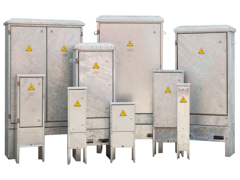
Feeder pillars may not be glamorous, but they are a pivotal - if often unsung - element of our street - level electrical infrastructure. With more and more municipalities embracing complex electrical equipment and CMS componentry.
FEEDER PILLAR
The inclusion of complex electrical equipment and CMS (Central Management System) technical componentry has tended to favour a “boxes” within “boxes” approach and not without good reason. This article explores some of the contradictions that are in pillar design and construction and questions whether we have got it right.It is often stated a feeder pillar is a just feeder pillar. However, in today’s complex street scene, this often-overlooked housing is critical, not just to an individual component of a scheme but very often to the scheme as a whole.
Though telecoms and traffic signal cabinets are generally made out of aluminium and in some cases GRP (Glass Re-enforced Plastic), their siting by definition is in areas of population and or areas that are highly trafficked. Vandalism and deterioration have not been seen as a problem.
In the last forty to fifty years, public lighting feeder pillar standards have migrated from cast iron, brick constructed and precast concrete to galvanised steel. Galvanised steel is the material that is familiar to
the lighting column specifiers and so by definition if the material thickness is similar to lighting columns, the feeder pillar body should have the same or better life span than lighting columns, particularly as it should not be as stressed since it is not being asked to work as a cantilever.
So why do we see 3 mm and 5mm sheet steel feeder pillars when lighting column wall thickness is sometimes as little as 2.3mm?
The answer is due to the galvanising process. Most people have never visited a galvaniser let alone witnessed the immersion of a fabricated structure into a bath at circa 450 degrees.
TEMPERATURE SHOCK
The Effect of the immersion can expand the material and consequently some pillars that you see will show evidence of distortion, particularly in wide flat panels. The Galvanisers Association do have an excellent wall chart that gives guidance on methods of manufacture and reinforcement strategies. Sadly, some of the solutions are not be suitable for feeder pillar purposes due to the cosmetic effects of the design changes required.It is a brutal process and even if the pillar shell is preheated prior to processing to reduce temperature shock, the temperature difference at immersion is still significant.
Galvanising is a protective rather than a cosmetic coating and though the European galvanising standard BS EN ISO 1461 (2009) does control surface finish, undulations will generally show through a painted topcoat.
Ingress protection of the entire pillar to IP65 or higher is often cited as a desirable specification to achieve. Delve down into most feeder pillar suppliers’ small print and it will have words to the effect of “door seal to IP65”. The rest of the cabinet is usually covered by a lower specification such as IP42 since ventilation panels may be placed in the doors, the sides or back. And what about the lid, apron and root? The author has yet to see these items fitted with gaskets or seals on any manufacturer’s offerings, except on very rare requests from clients with specific objectives. Count these as ventilation and then the pillar meets the stated IP42 specification.
(it is not the purpose of this article to further explore the vagaries of Ingress Protection ratings here, other than to guide readers to BS EN 60529 (1992) and suggest they read it in full).
HINGE SYSTEM
Hinge systems for Pillars are normally made from stainless steel of 304 or 316 grade. This should give decades of use without trouble were it not for a peculiar characteristic of stainless steel known as “Galling” which is a cold welding of two surfaces of stainless steel within the hinge that can render a door movement impossible without destroying it. The lack of frequency that the doors are opened can only exacerbate this as can the application of grease or lubricating fluids that may attract grit and dust that may be a catalyst for the problem. One manufacturer uses a silicon bronze and stainless steel hinge combination to mitigate this particular problem as it is a recognized non-lubricated bearing method. However, this solution is sometimes rejected as the contrast in colour is not as cosmetically attractive.
Pillars are often supplied with proprietary locks that look as though they are stainless steel, but in fact are chrome plated over a sintered zinc die casting. This is a manufacturing system where a zinc powder compound is compacted at high temperature in a very high-pressure mould. In the Author’s experience these locks have a limited life, particularly on the coast, but are very inexpensive to purchase and replacements are available worldwide. The proprietary lock suppliers often duplicate their ranges in stainless, however this can be at a price point of ten times or more of the standard item.
The integrity of locking systems is often the first failure point of a feeder pillar and it is not unusual to see feeder pillar doors banded. However, feeder pillar suppliers of any credibility should be able to supply both stainless steel locks and replacement locks for their range of pillars as well as any supplied in the last twenty years regardless of warranty conditions, and so it should not be necessary to band doors.
Occasionally pillars are requested with “Yale” type key cylinders. These will work very well for doors such as domestic front doors which are opened regularly. However, where the doors are opened rarely, maybe annually or every three to five years, then their use is not to be encouraged. The keys being an alloy are limited in their robustness and should there be any unwanted interference with the key cavity, such as the inclusion of a matchstick or superglue or even grit, then there is not a lot of guidance or help that the pillar supplier will be able to give.
The construction of Feeder Pillars with separate roots is a bit of a conundrum as the theory is that any pillars damaged can be lifted off and replaced without changing the root. However, in the author’s experience of pillar manufacture this is not a sensible option for two reasons. Firstly, the removal of the fastenings at ground level on an internal flange within a root section, working in the immediate vicinity of rigid and possibly live cables is at best difficult and should be deemed a high enough risk not to be undertaken. Secondly, in the case of vehicular impact the horizontal flanges may cut through the supply cables upstream of the control equipment the pillar is housing. This makes the siting of pillars extremely important. Obviously, the cabinet can only be sited in a position where the supply is accessible on retrofit installations, but unfortunately, the likely run off areas for errant drivers when they decide to drive adjacent to the road is not always considered correctly.
Vandalism may be an overstated risk in todays interconnected society. The current design of feeder pillars is often defined by the “hinged door fitted within a frame” phrase. This dates back about 30 years to the days of Strathclyde Regional Council who had a particular and specific challenge with unauthorised entry.
SPECIFY SPARE SPACE
Written by Peter Diamond
This system is better than some overlapping door designs, however the author believes any manufacturer’s feeder pillar can be opened with a crowbar within seconds. Fortunately crowbars are a relatively rare implement today so this risk may be very small.
An undesirable by-product of the framed door design is that every pillar is about 6 inches wider than it needs to be for the internal equipment to be placed within it, as it has to pass through the door opening. On larger pillars this is not significant but when smaller pillars are placed in towns and cities this is a significant increase in width and cost that conflicts with the ideals of minimum footprint and economic purchase.
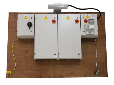
Specifications often require feeder pillars to be supplied with 25% spare space. This can be interpreted in several ways. Some customers are happy that this can be any space on the backboard of the pillar. It is clear for us, as a supplier, that the designer wishes for the pillar to be expandable should extra capacity be required in the future. In order to ensure that the correct product is supplied, the specification should state that the width on the backboard should be with 25% spare space, or alternatively that the distribution board within the pillar should have 25% spare ways.
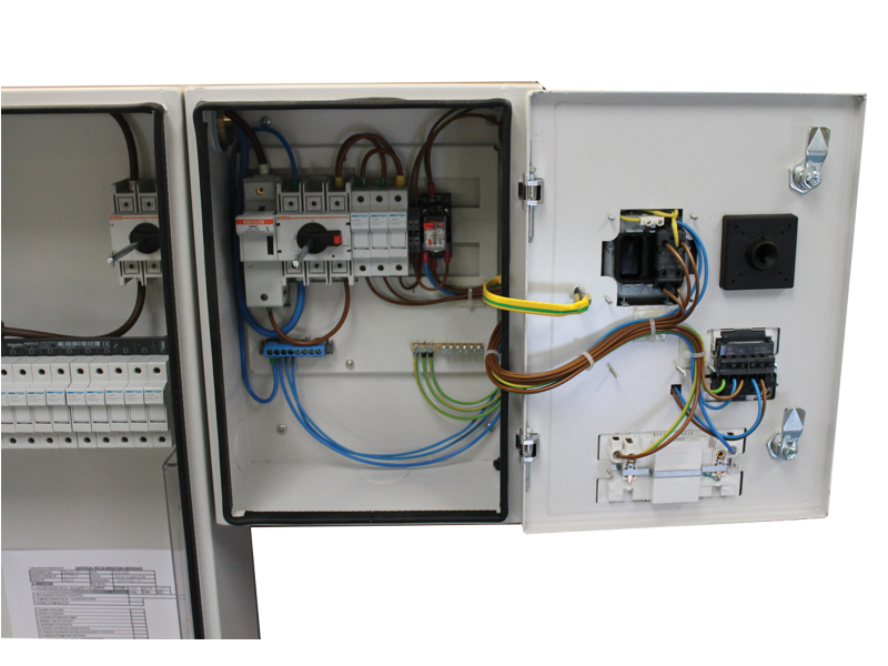
Fortunately, the days of empty feeder pillars turning up on site with the installer having to purchase the componentry separately and install the components at the roadside have largely disappeared. Most pillar suppliers have proprietary box systems using branded equipment that are well developed and can offer economic and reliable distribution systems from schematics that are fully tested and certified before they leave the factory.
As with many areas of business and life the reality is that a properly designed and engineered feeder pillar may cost a little more, but quality and longevity is key. The long-term cost as opposed to the price may not always be understood at the time of proposal.
Written by Peter Diamond